Our Busbar Supports are standardized with a fire protection rating of UL 94 V0 and type-tested according to DIN EN 61439-1.
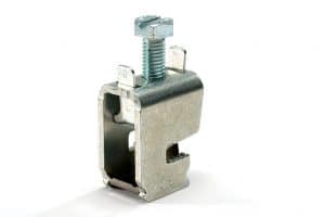
Busbar supports are standardized mounting devices for busbars used for the central distribution of electrical energy in switchgear and distribution boxes. They are used to securely fasten and fix the busbars.
Thanks to the flexible mounting options, the holders can be mounted on the ceiling, wall, or floor and can therefore be universally used horizontally or vertically. Due to their high inherent mechanical strength, no additional substructures are required.
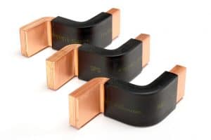
The clamps of the Busbar Supports are made of glass-fiber reinforced plastic and have fire protection class UL 94 V0. The steel profiles are of grade DX51D + Z275 and are coated with epoxy-polyester powder.
Approvals
Fire protection class UL 94 V0
Standards
RoHS, CE, REACH
Type-tested according to DIN EN 61439-1

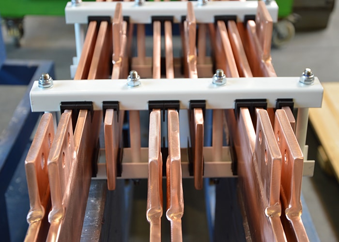
The hangers are simply suspended using the integrated threaded rods. No additional screw connections are required. Additional holes are provided in the hanger so that the entire hanger can be suspended using additional threaded rods. The individual busbars are attached to plastic clamps and can thus be easily fastened. Our busbar hangers are available with 3 or 4 phases. Depending on the power requirement, 1 to 3 bars per phase can be varied.
The bar lengths can be varied depending on the number of phases, the number of busbars per phase and the arrangement.
There are no restrictions here. SPS busbar supports are suitable for bar thicknesses of 10 mm and bar widths of 40, 50, 60, 80, 100 or 120 mm.

By affixing the CE marking, the manufacturer, distributor or EU representative declares, in accordance with Regulation (EC) No. 765/2008, that the product meets the applicable requirements set out in the Community harmonization legislation providing for its affixing.

| SPS Artikelnr. / Item no. | Phasen / Phases | Schienen pro Phase / Bars per Phase | Schienen-Breite / Bar Width [mm] | Phasenmitten-Abstand / phase center distance [mm] | Querschnitt / Cross-section [mm²] | Bemessungs-Strom / Rated current [A] > | IpK [kA] (600mm*) | Icw 1s [kA] (600mm*) | IpK [kA] (300mm*) | Icw 1s [kA](300mm*) |
|---|---|---|---|---|---|---|---|---|---|---|
| 90.022.040 | 3 | 1 | 40 | 70 | 400 | 700 | 110 | 50 | 140 | 70 |
| 90.022.045 | 4 | 1 | 40 | 70 | 400 | 700 | 110 | 50 | 140 | 70 |
| 90.022.040 | 3 | 1 | 50 | 70 | 500 | 850 | 110 | 50 | 140 | 70 |
| 90.022.045 | 4 | 1 | 50 | 70 | 500 | 850 | 110 | 50 | 140 | 70 |
| 90.022.040 | 3 | 1 | 60 | 70 | 600 | 950 | 110 | 50 | 140 | 70 |
| 90.022.045 | 4 | 1 | 60 | 70 | 600 | 950 | 110 | 50 | 140 | 70 |
| 90.022.040 | 3 | 1 | 80 | 70 | 800 | 1.200 | 110 | 50 | 140 | 70 |
| 90.022.045 | 4 | 1 | 80 | 70 | 800 | 1.200 | 110 | 50 | 140 | 70 |
| 90.022.040 | 3 | 1 | 100 | 70 | 1000 | 1.450 | 110 | 50 | 140 | 70 |
| 90.022.045 | 4 | 1 | 100 | 70 | 1000 | 1.450 | 110 | 50 | 140 | 70 |
| 90.022.040 | 3 | 1 | 120 | 70 | 1200 | 1.700 | 110 | 50 | 140 | 70 |
| 90.022.045 | 4 | 1 | 120 | 70 | 1200 | 1.700 | 110 | 50 | 140 | 70 |
| 90.022.050 | 3 | 2 | 40 | 110 | 800 | 1.250 | 110 | 50 | 140 | 70 |
| 90.022.055 | 4 | 2 | 40 | 110 | 800 | 1.250 | 110 | 50 | 140 | 70 |
| 90.022.050 | 3 | 2 | 50 | 110 | 1000 | 1.500 | 110 | 50 | 140 | 70 |
| 90.022.055 | 4 | 2 | 50 | 110 | 1000 | 1.500 | 110 | 50 | 140 | 70 |
| 90.022.050 | 3 | 2 | 60 | 110 | 1200 | 1.700 | 110 | 50 | 140 | 70 |
| 90.022.055 | 4 | 2 | 60 | 110 | 1200 | 1.700 | 110 | 50 | 140 | 70 |
| 90.022.050 | 3 | 2 | 80 | 110 | 1600 | 2.100 | 165 | 80 | 180 | 90 |
| 90.022.055 | 4 | 2 | 80 | 110 | 1600 | 2.100 | 165 | 80 | 180 | 90 |
| 90.022.050 | 3 | 2 | 100 | 110 | 2000 | 2.450 | 165 | 80 | 180 | 90 |
| 90.022.055 | 4 | 2 | 100 | 110 | 2000 | 2.450 | 165 | 80 | 180 | 90 |
| 90.022.050 | 3 | 2 | 120 | 110 | 2400 | 2.850 | 165 | 80 | 180 | 90 |
| 90.022.055 | 4 | 2 | 120 | 110 | 2400 | 2.850 | 165 | 80 | 180 | 90 |
| 90.022.060 | 3 | 3 | 40 | 110 | 1200 | 1.750 | 110 | 50 | 140 | 70 |
| 90.022.065 | 4 | 3 | 40 | 110 | 1200 | 1.750 | 110 | 50 | 140 | 70 |
| 90.022.060 | 3 | 3 | 50 | 110 | 1500 | 2.000 | 110 | 50 | 140 | 70 |
| 90.022.065 | 4 | 3 | 50 | 110 | 1500 | 2.000 | 110 | 50 | 140 | 70 |
| 90.022.060 | 3 | 3 | 60 | 110 | 1800 | 2.250 | 165 | 80 | 180 | 90 |
| 90.022.065 | 4 | 3 | 60 | 110 | 1800 | 2.250 | 165 | 80 | 180 | 90 |
| 90.022.060 | 3 | 3 | 80 | 110 | 2400 | 2.750 | 165 | 80 | 180 | 90 |
| 90.022.065 | 4 | 3 | 80 | 110 | 2400 | 2.750 | 165 | 80 | 180 | 90 |
| 90.022.060 | 3 | 3 | 100 | 110 | 3000 | 3.250 | 165 | 80 | 180 | 90 |
| 90.022.065 | 4 | 3 | 100 | 110 | 3000 | 3.250 | 165 | 80 | 180 | 90 |
| 90.022.060 | 3 | 3 | 120 | 110 | 3600 | 3.700 | 165 | 80 | 180 | 90 |
| 90.022.065 | 4 | 3 | 120 | 110 | 3600 | 3.700 | 165 | 80 | 180 | 90 |
| Bemessungs-Strom / Rated current [A] > |
*Indicates the distance from support to support.
Busbar Supports are used to securely and stably attach busbars to walls, ceilings or other structures.
They are designed to withstand the forces of a short circuit, even in an emergency. Busbars are used to distribute electricity and are frequently used in industrial plants, but also in buildings.
Busbar Supports are usually fixed in place by bolting or doweling, although hanging installation is also possible.
The exact method of attachment depends on the type of substrate and the fastening.
The load capacity of a Busbar Support depends on various factors, such as the material, the design, and the distance between two supports.
We specify the maximum permissible load as short-circuit strength.
Busbar Supports are sized according to the load to be carried and the ambient conditions.
You are currently viewing a placeholder content from Vimeo. To access the actual content, click the button below. Please note that doing so will share data with third-party providers.
More InformationYou are currently viewing a placeholder content from YouTube. To access the actual content, click the button below. Please note that doing so will share data with third-party providers.
More InformationYou need to load content from reCAPTCHA to submit the form. Please note that doing so will share data with third-party providers.
More InformationYou are currently viewing a placeholder content from Vimeo. To access the actual content, click the button below. Please note that doing so will share data with third-party providers.
More InformationYou are currently viewing a placeholder content from YouTube. To access the actual content, click the button below. Please note that doing so will share data with third-party providers.
More InformationYou are currently viewing a placeholder content from Bunny Stream. To access the actual content, click the button below. Please note that doing so will share data with third-party providers.
More InformationYou are currently viewing a placeholder content from Wistia. To access the actual content, click the button below. Please note that doing so will share data with third-party providers.
More InformationYou are currently viewing a placeholder content from Facebook. To access the actual content, click the button below. Please note that doing so will share data with third-party providers.
More InformationYou are currently viewing a placeholder content from Instagram. To access the actual content, click the button below. Please note that doing so will share data with third-party providers.
More InformationYou need to load content from hCaptcha to submit the form. Please note that doing so will share data with third-party providers.
More InformationYou need to load content from reCAPTCHA to submit the form. Please note that doing so will share data with third-party providers.
More InformationYou are currently viewing a placeholder content from Turnstile. To access the actual content, click the button below. Please note that doing so will share data with third-party providers.
More InformationYou are currently viewing a placeholder content from X. To access the actual content, click the button below. Please note that doing so will share data with third-party providers.
More Information